Protective conductor contact, clock position and plug colours
Rated voltage over 50 V
Rated voltage over 50 V requires
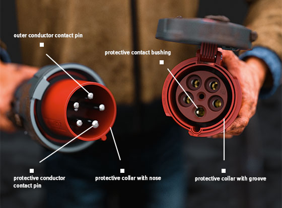
- a plug with a protective conductor contact with contact pin and a protective collar with secondary key slot
- a connector or socket with a protective conductor contact with contact bushing and a protective collar with groove.

The protective contact pin of the plug has a larger diameter than the outer conductor and neutral conductor pins - that way it only fits into the approriate protective conductor bushing in the connector or receptacle. This specific structure and the fixed position of the protectice collar groove on the plug (must not be changed or removed) and the respective protective collar nose in the connector/receptacle prevents wrong connecting of plug and connector/receptacle and potentially fatal incidents with high voltages.
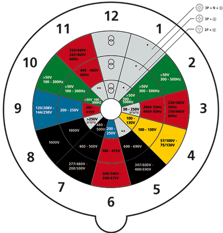
Clock positions

The clock position indicates the location of the prodective conductor contact on the live end of any plug and socket - the examplary picture above shows a connector with the clock position 6h.
The colours of a plug indicate the rated voltage. Most red plugs are made for voltages between 380 and 480 V - like the three-phase alternating current (400 V) in Germany, black plugs are designed for industries, blue plugs for household appliances, yellow plugs for safety voltage on ships and green plugs for construction machinery.
Further information
On rewirable plugs and sockets the contacts must be marked with symbols as follows:
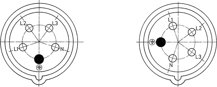
- Where there are three phase conductors the phase contacts are to be marked L1, L2, L3 or 1, 2, 3; the neutral contact (if present) is to be marked N and the earth contact is to be marked ⏚.
- Where there is one phase conductor the live pole L/+ is to be marked with a symbol ⏚ for the earth contact, if applicable.
The contact tubes of receptacles and connectors with rated voltages above 50 V must be arranged clockwise as viewed from the front.
Typ | Frequency | Rated operating voltage | Position of ground contact 1) | |
Hz | V | 16/20 A* | 63/60 A* | |
1 p + N + E | 50 and 60 | 100 to 130 | 4 | 4 |
60 | 277 | 5 | 5 | |
2 p + E | 50 and 60 | 100 to 130 | 4 | 4 |
200 to 250 | 6 | 6 | ||
380 to 415 | 9 | 9 | ||
480 to 500 | 7 | 7 | ||
with isolating transformer | 12 | 12 | ||
100 to 300 | above 50 | 10 | 10 | |
above 300 to 500 | above 50 | 2 | 2 | |
DC | above 50 to 250 | 3 | 3 | |
above 250 | 8 | 8 | ||
2 p + N + E* | 50 and 60 | 125/250 single phase | 12 | 12 |
2 p + N + E | 50 and 60 | with isolating transformer | 12 | 12 |
3 p + E | 50 and 60 | 100 to 130 | 4 | 4 |
200 to 250 | 9 | 9 | ||
380 to 415 | 6 | 6 | ||
60 | 440 to 460 2) | 11 | 11 | |
50 and 60 | 480 to 500 | 7 | 7 | |
600 to 690 | 5 | 5 | ||
50 | 380 | 3 | 3 | |
50 and 60 | 1000 | - | 8 | |
100 and 300 | above 50 | 10 | 10 | |
above 300 to 500 | above 50 | 2 | 2 | |
3 p + N + E | 50 and 60 | 57/100 to 75/130 | 4 | 4 |
120/208 to 144/250 | 9 | 9 | ||
200/346 to 240/415 | 6 | 6 | ||
277/480 to 288/500 | 7 | 7 | ||
347/600 to 400/690 | 5 | 5 | ||
60 | 250/440 to 265/460 2) | 11 | 11 | |
50 and 60 | with isolating transformer | 12 | 12 | |
50 | 220/380 | 3 | 3 | |
100 to 300 | above 50 | 10 | 10 | |
above 300 to 500 | above 50 | 2 | 2 | |
All types | All rated voltages and all frequencies not covered by other configurations | 1 | 1 | |
* Series II devices are primarily used in the US and Canadian markets. | ||||


